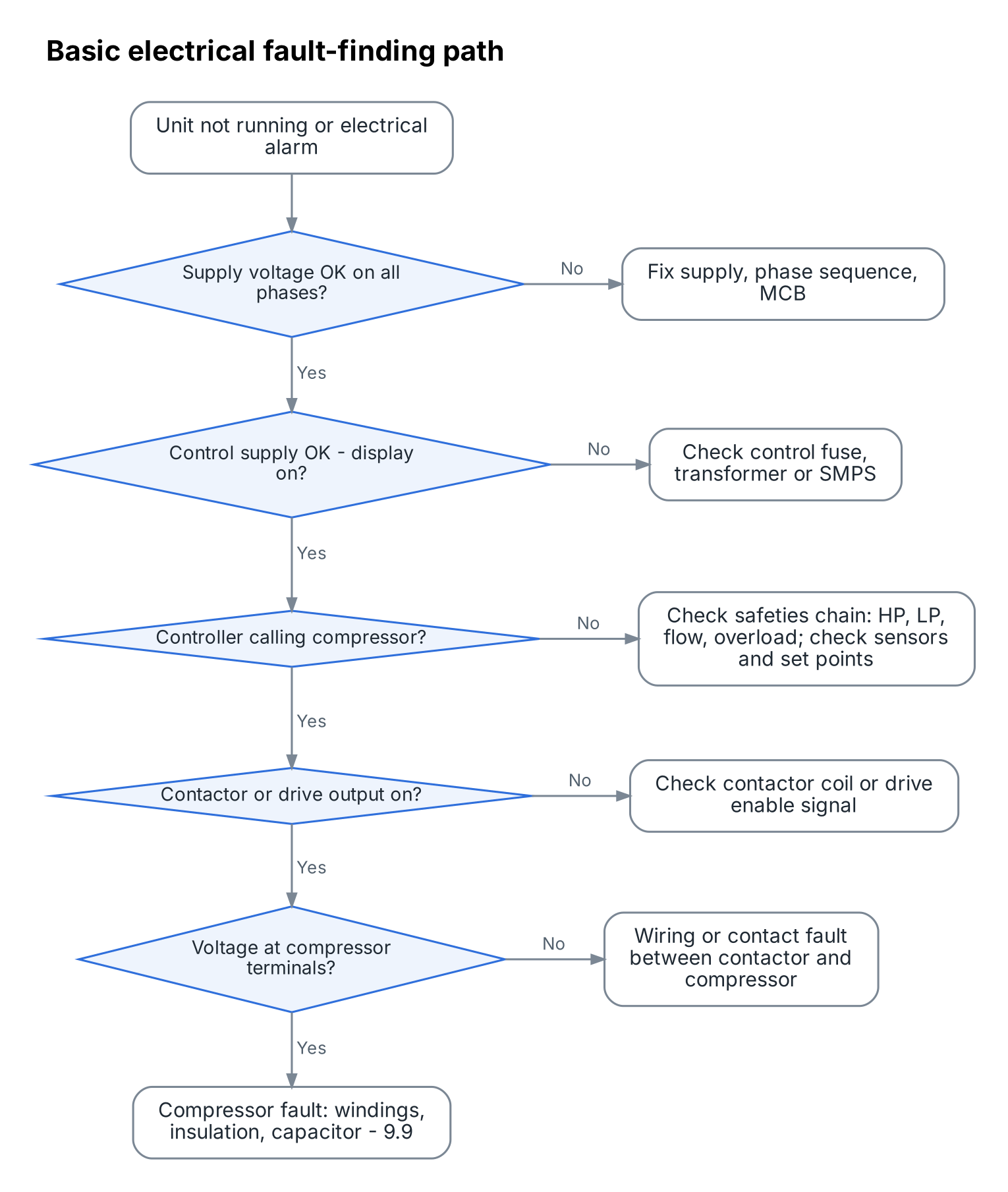
9.11 Electrical and control faults
The electrical side has two parts. The power circuit carries high current to the compressor, fans and pump through MCBs (miniature circuit breakers), contactors and drives. The control circuit carries small signals from sensors, switches and the controller.
Indian sites often face voltage swings, missing phases and loose terminals from heat and vibration. A loose terminal heats up like a bad plug on an iron, until it burns.
Safety first: Isolate, lock out and prove dead with a tested voltage tester before touching terminals. Capacitors and inverter drives can hold dangerous charge after power is off; wait the time stated on the drive and measure.
Common electrical and control faults
| Symptom | Likely cause | Check | Fix |
|---|---|---|---|
| Unit dead, no display | No supply, tripped MCB, blown control fuse, failed transformer/SMPS | Voltage at incoming terminals and control supply | Restore supply, find why it tripped, replace fuse/PSU |
| Phase fault alarm | Missing phase or wrong phase sequence | Voltage each phase, phase sequence meter | Fix supply; swap two phases if sequence wrong (fixed-speed scroll) |
| Compressor hums, will not start (single-phase) | Failed run/start capacitor, low voltage, seized rotor | Capacitor µF vs rating, voltage at start | Replace capacitor; check voltage; condemn if seized |
| Contactor chatters | Low coil voltage, loose control wire | Coil voltage, terminals | Tighten, fix supply to coil |
| Burnt contactor contacts | Normal wear, frequent starts, low voltage | Inspect contacts, starts per hour | Replace contactor; reduce short cycling |
| Sensor fault code | Open or short sensor, damp connector | Sensor resistance vs temperature table | Dry, re-terminate or replace sensor |
| Wrong temperature shown | Sensor out of pocket, poor contact | Compare with reference thermometer | Refit with paste and insulation; replace |
| Communication fault | Loose cable, poor earth, interference from power cables | Cable continuity, routing, shield earthing | Re-route away from power cables, earth shield at one end |
| Inverter drive trip | Supply problem, overheated drive, motor fault | Heat sink fan, ambient, motor winding test | Clean and cool drive; fix supply; follow drive manual |
| Flow switch fault but water flowing | Paddle stuck, switch misadjusted | Switch contact operation | Clean, adjust or replace |
| Earth leakage (RCCB) trips | Insulation failure, water in junction box | Insulation test on each motor and heater | Dry out or replace faulty part |
Worked example — Check an NTC sensor
An NTC (negative temperature coefficient) thermistor's resistance falls as temperature rises. Many heat pump sensors are 10 kΩ at 25 °C (typical), but the table depends on the sensor.
Water is at 40 °C (measured with a reference thermometer). The sensor's resistance table shows about 5.3 kΩ at 40 °C for a typical 10 kΩ B3950 sensor. The meter reads 5.2 kΩ: the sensor is good.
If the meter reads infinity (open circuit) or near zero (short), the sensor or its wire has failed. Always use the resistance table for the actual sensor fitted.

With R₂₅ = 10 kΩ, B = 3950 K, T = 313.15 K: 1/313.15 − 1/298.15 = 0.0031934 − 0.0033540 = −0.0001606 B × (−0.0001606) = −0.6345 R = 10 × e^(−0.6345) = 10 × 0.530 = 5.3 kΩ.
Remember
- Isolate, lock out and prove dead before touching terminals.
- Check supply and phases early in any fault.
- Test sensors against their resistance table.
- Keep signal cables away from power cables.
Many "refrigeration" faults are really electrical or control faults, so check power, signals and sensors early.
There are no comments for now.
to be the first to leave a comment.