7.4 Water piping layout and sizing
Flow rate is how much water passes per hour (m³/h or LPH, litres per hour). Velocity is how fast it moves in the pipe (m/s). Too fast is noisy and erodes fittings. Too slow lets air and dirt settle, and the pipe costs more than needed.
A typical heat pump circuit runs at a temperature difference (ΔT) of about 5 K between flow and return. The heat carried depends on flow and ΔT.
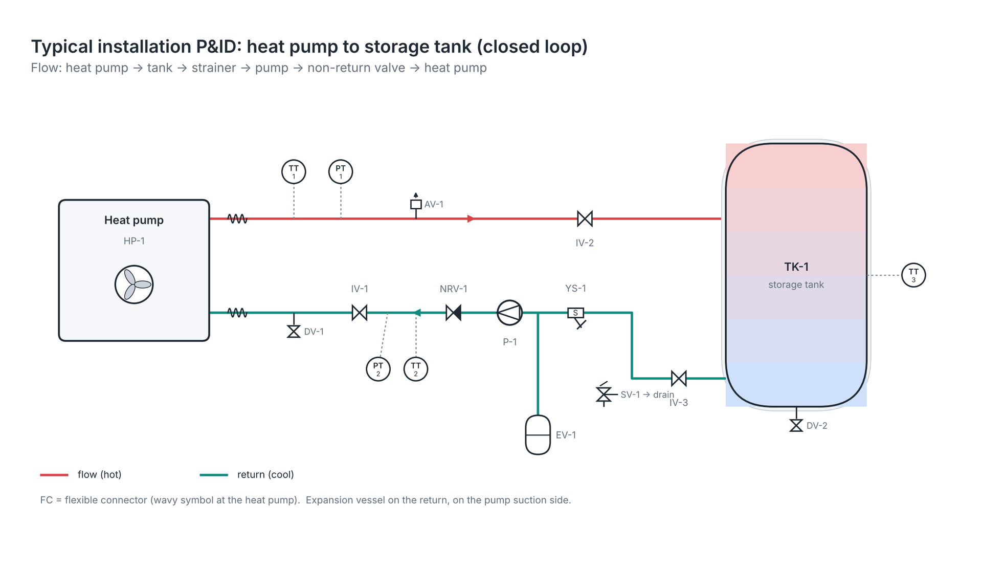
Flow direction: heat pump → flow pipe → tank coil / tank → return pipe → strainer → pump → non-return valve → heat pump.
| Tag | Item | Purpose |
|---|---|---|
| HP-1 | Heat pump | Heat source |
| TK-1 | Storage tank | Stores hot water, buffers load |
| IV-1/2/3 | Isolation valve (ball valve) | Isolate unit or tank for service |
| FC-1/2 | Flexible connector | Stop vibration reaching pipes; allow small movement |
| YS-1 | Y-strainer | Catch dirt and scale before pump and heat exchanger |
| P-1 | Circulation pump | Moves water around the loop |
| NRV-1 | Non-return valve | Stops reverse flow when pump stops |
| EV-1 | Expansion vessel | Absorbs water expansion as it heats |
| SV-1 | Safety (relief) valve | Opens if pressure rises above set point |
| AV-1 | Automatic air vent | Releases trapped air at high point |
| DV-1/2 | Drain valve | Empty and flush the system |
| TT-1/2/3 | Temperature transmitter / test point | Read flow, return and tank temperatures |
| PT-1/2 | Pressure transmitter / gauge point | Read pressure; across strainer and unit shows blockage |
Typical pipe sizing table
Water flow at typical velocities of 0.7–1.5 m/s, based on typical internal diameters of medium-grade steel pipe. Copper and PPR (polypropylene random copolymer) pipes have different internal diameters, so check the maker's chart. These are typical guides, not design values.
| Nominal size | Typical ID (mm) | Flow at 0.7 m/s (m³/h) | Flow at 1.5 m/s (m³/h) | Approx. heat at ΔT 5 K, upper flow (kW) |
|---|---|---|---|---|
| DN15 (½") | 16 | 0.5 | 1.1 | 6 |
| DN20 (¾") | 22 | 0.9 | 2.0 | 11 |
| DN25 (1") | 27 | 1.5 | 3.2 | 18 |
| DN32 (1¼") | 36 | 2.6 | 5.5 | 32 |
| DN40 (1½") | 42 | 3.5 | 7.5 | 43 |
| DN50 (2") | 53 | 5.6 | 12.0 | 70 |
| DN65 (2½") | 69 | 9.4 | 20.1 | 117 |
| DN80 (3") | 81 | 13.0 | 27.8 | 160 |
| DN100 (4") | 105 | 21.9 | 47.0 | 270 |
Small pipes near homes are best kept at the lower end of velocity for quiet running.
Worked example — size the pipe for a 30 kW heat pump at a Bengaluru hotel
The unit heats at 30 kW with ΔT = 5 K.

- Flow: 30 ÷ (1.163 × 5) = 30 ÷ 5.815 = 5.16 m³/h (5,160 LPH).
- Try DN32 (ID 0.036 m): area = 0.7854 × 0.036² = 0.00102 m². Velocity = 5.16 ÷ (3,600 × 0.00102) = 1.41 m/s. Upper end, possible but noisier.
- Try DN40 (ID 0.042 m): area = 0.7854 × 0.042² = 0.00139 m². Velocity = 5.16 ÷ (3,600 × 0.00139) = 1.03 m/s. Comfortable.
- Choose DN40 for the main run. The unit's own connection may be smaller; reduce only at the unit.
(1.163 is the heat in Wh needed to warm 1 litre of water by 1 K.)
Remember
- Flow = kW ÷ (1.163 × ΔT); then pick a pipe for about 0.7–1.5 m/s.
- Strainer and pump on the return, before the heat pump.
- Air vents at high points, drains at low points.
- Fit TT and PT points on flow and return for commissioning.
The water side must carry the right flow at a sensible velocity, with every component in its correct place.
There are no comments for now.
to be the first to leave a comment.