8.4 Measuring temperature, pressure, flow and power
To prove performance on site you need a measured heat output and a measured electrical input. Heat output comes from water flow and temperature rise. Electrical input comes from a power meter.
Each instrument must sit in the right place. A temperature sensor placed after a mixing tee, or a flow meter right after a bend, gives a wrong reading. The P&ID below shows where every test instrument goes. A P&ID (piping and instrumentation diagram) is a drawing that shows pipes, valves and instruments with standard symbols and tags.
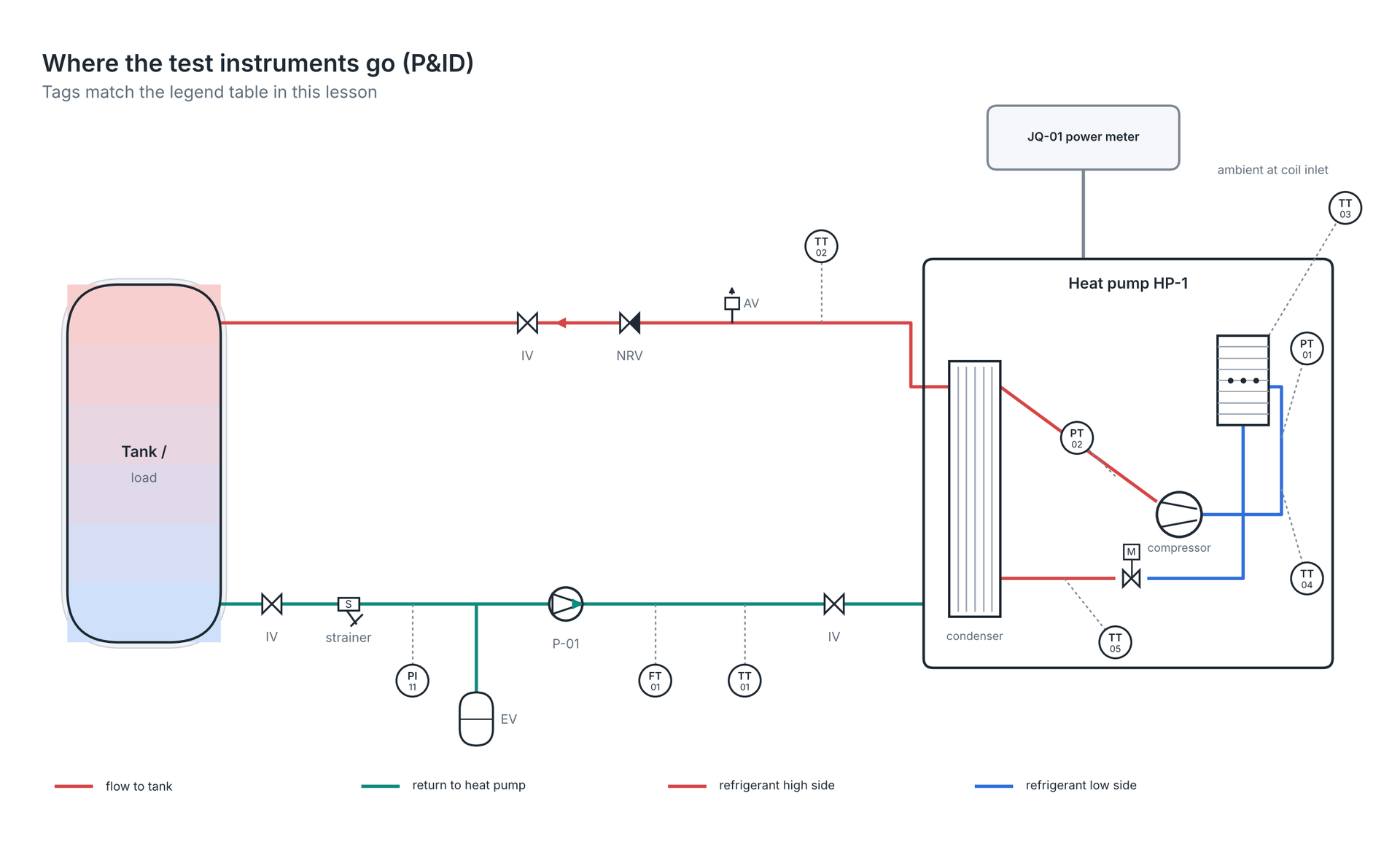
Legend (table under the diagram):
| Tag / symbol | Meaning | Where it goes |
|---|---|---|
| TT-01 | Temperature transmitter, inlet water | Pipe into heat pump, after pump and flow meter, close to unit |
| TT-02 | Temperature transmitter, outlet water | Pipe out of heat pump, before any tee or mixing |
| TT-03 | Ambient air temperature | Shaded, at the air inlet of the coil, not in exhaust air |
| TT-04 | Suction line temperature | Suction pipe near compressor, insulated over sensor |
| TT-05 | Liquid line temperature | Liquid pipe after condenser, insulated over sensor |
| FT-01 | Flow transmitter / flow meter | Straight pipe run on inlet side |
| PT-01 | Suction pressure | Suction service port |
| PT-02 | Discharge pressure | Discharge / high-side service port |
| PI-11 | Water pressure gauge | Return line, near pump suction |
| JQ-01 | Power and energy meter | Electrical supply feeding the whole unit |
| P-01 | Circulating pump | Return line to heat pump |
| IV | Isolation valve | Both sides of heat pump |
| NRV | Non-return valve | Flow line, prevents back-flow |
| AV | Automatic air vent | High point of circuit |
| EV | Expansion vessel | Return line, pump suction side |
| Strainer | Y-strainer | Before pump and heat pump inlet |
| Measurement | Instrument | Typical accuracy needed | Placement rule |
|---|---|---|---|
| Water temperature | PT100 Class A or calibrated thermistor in a thermowell | ±0.2 °C or better | Immersed in flow, thermowell filled with paste |
| Air temperature | Shaded probe | ±0.5 °C | At coil inlet, out of sun |
| Water flow | Electromagnetic or ultrasonic flow meter | ±1–2% | Straight run, typical 10 D upstream and 5 D downstream |
| Refrigerant pressure | Digital manifold | ±0.5% of full scale | Service ports, hoses purged |
| Refrigerant pipe temperature | Clamp probe | ±0.5 °C | Clean pipe, insulated over probe |
| Electrical power | True-RMS power meter (kW, kWh) | ±1% | On the unit supply, all phases |
Why ±0.2 °C matters: with a 5 K water ΔT, an error of 0.2 °C on each sensor can shift ΔT by 0.4 K. That is an 8% error in capacity before you even start.
Remember
- Measure the water ΔT with matched, calibrated sensors, not the unit's own display alone.
- Ultrasonic clamp-on meters need a straight pipe and correct pipe data.
- Measure power with a true-RMS meter on all phases; amps alone are not watts.
- Place the ambient probe where the coil actually breathes, in shade.
A capacity or COP figure is only as good as the four measurements behind it — temperature, flow, pressure and power.
There are no comments for now.
to be the first to leave a comment.