SE-EVI-150V
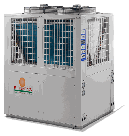
Enhanced vapour injection heat pump for cold climates — rated hot water to 60 °C with the ambient as low as −20 °C. R410A scroll circuit, three-phase.
Performance
Rated output at each published test condition- Heating capacity
- 150kW
- Power input
- 39.4kW
- COP
- 3.8
- Hot water output
- 3225LPH
- Heating capacity
- 100.4kW
- Power input
- 38.7kW
- COP
- 2.6
- Hot water output
- 1880LPH
- Heating capacity
- 74.6kW
- Power input
- 48kW
- COP
- 1.6
- Hot water output
- 1400LPH
Technical specifications
SE-EVI-150V| Parameter | Unit | Specification |
|---|---|---|
| Electrical supply | ||
| Power supply | — | 380~415 V / 50 Hz / 3 Ph |
| Rated current | A | 65.5 |
| Maximum current | A | 98.2 |
| Required MCCB | — | 125 A × 4 pole |
| Required cable | — | 4 core × 35 sq.mm copper cable + earthing |
| Refrigeration circuit | ||
| Compressor | — | Scroll (Copeland / Panasonic) |
| Number of compressors | Nos | 2 |
| Refrigerant | — | R410A |
| Heat exchanger (condenser) | — | Tube-in-shell / Brazed plate heat exchanger |
| Evaporator | — | Blue finned evaporator coil |
| Throttling device | — | Thermostatic / Electronic expansion valve |
| Fan quantity | Nos | 2 |
| Operating ambient range | °C | −25 to 43 |
| Water circuit | ||
| Rated water temperature | °C | 55 |
| Maximum water temperature | °C | 60 |
| Water flow | m³/hr | 25.8 |
| Water pressure drop | kPa | ≤ 57 |
| Water pipe size | inch | R2-1/2 |
| Unit & acoustics | ||
| Dimensions (L × W × H) | mm | 2240 × 1185 × 2060 |
| Net weight | kg | 570 |
| Noise at 1 metre | dB(A) | ≤ 62 |
Test conditions
- T1 — Ambient 20/15 °C (DB/WB), E.T. 10 °C, C.T. 60 °C
- T2 — Ambient 10 °C (DB), E.T. 0 °C, C.T. 60 °C
- T3 — Ambient 0/−2 °C (DB/WB), E.T. −20 °C, C.T. 60 °C
- T4 — Ambient −10/−10 °C (DB/WB), E.T. −20 °C, C.T. 60 °C
- T5 — Ambient −20/−20 °C (DB/WB), E.T. −30 °C, C.T. 60 °C
Installation requirement
- Dedicated 125 A × 4 pole MCCB required at the unit.
- Supply cable 4 core × 35 sq.mm copper, with separate earthing.
- Maintain water flow of 25.8 m³/hr; pressure drop across the unit ≤ 57 kPa.
Built to order
Options available on this modelOptions
- Water connection — Coupling type to suit the site — threaded, flanged or grooved.
- Casing — Stainless steel or powder-coated finish.
- Circulation pump — Can be built into the unit instead of being fitted in the plant room.
- Condenser — Stainless steel or copper, in place of the standard build.
How to order them
- None of the above is the standard build, and none of it is included in the specification table on this page.
- Ask for it at enquiry and have it confirmed in writing on the order acknowledgement. Price, lead time and weight can all change with it.
The table above describes the standard machine. Options are quoted per order and are available across the range except on the All-in-One and Split units.
Site installation schematic
How the unit connects to the tank, pumps and piping on site- 1Heat pump unit
- 2RCC foundation with anti-vibration pads
- 3Insulated storage tank
- 4Primary circulation pump
- 5Y-strainer
- 6Non-return valve
- 7Isolation valve (typical)
- 8Automatic air vent
- 9Safety / pressure-relief valve
- 10Tank sensor to heat pump controller
- 11Drain valve
- 12Cold water feed
- 13Hot water to usage points
- 14Recirculation (return-line) pump
- 15Thermometer
- 16Power supply / MCB panel
Indicative hookup only. Static head, draw pattern and local code may call for additional components — confirm the final scheme with Sunniva before ordering.
Selection & site preparation
Recommended sizing derived from this model’s rated data| Storage tank volume | 6450 – 19350 L |
| Tank sizing rule | Hot water output × 2 to 6 LPH measured at 20 °C ambient. Indicative range — stay inside it so the tank is neither undersized nor oversized. |
| Primary circulation pump | 27.5 m³/hr @ 10 – 12 m head |
| Recirculation (return) pump | 3.1 – 3.9 m³/hr @ 6 – 8 m head |
| Primary pipe size | 65 mm (R2-1/2) to 10 m run; 80 mm beyond |
| Line insulation | 25 mm closed-cell, every line above 45 °C |
| Unit footprint & dry weight | 2240 × 1185 mm · 570 kg |
| Heat pump plinth | 2390 × 1335 × 150 mm RCC, M20 |
| Plinth level | 100 mm above finished floor, ± 3 mm/m |
| Tank pad (6450 L) | 150 mm RCC, 200 mm larger each side ≈ 7417 kg filled |
| Clearances | 1000 mm air-on · 1500 mm above fan · 1000 mm service side |
| Electrical | 125 A × 4 pole MCCB · 4 core × 35 sq.mm copper cable + earthing |
Installation steps
Follow in order — a commissioning engineer should sign off before start-up- Cast the RCC plinth 2390 × 1335 × 150 mm in M20 concrete, 100 mm above finished floor. Let it cure and check it is level within 3 mm per metre.
- Set the unit down on anti-vibration pads. Keep 1000 mm clear at the finned coil faces and 1500 mm above the fan — the unit must breathe or capacity drops.
- Place the tank on its own level pad, as close to the heat pump as the site allows. Short pipes lose less heat.
- Pipe tank bottom → isolation valve → Y-strainer → primary pump → heat pump inlet, in that order. Fit the non-return valve after the pump.
- Pipe the heat pump outlet → tank top inlet. Fit an isolation valve at each end so the unit can be serviced without draining the tank.
- Fit the automatic air vent and the safety valve on the tank top. Pipe the safety valve discharge to an open drain — never cap it.
- Bring the cold water feed into the tank bottom through an isolation valve and a non-return valve.
- Fit the tank sensor into the tank pocket and run its cable back to the heat pump controller. Do not run it alongside the power cable.
- Insulate every hot line with 25 mm closed-cell insulation, pump body included.
- Power the unit from a dedicated 125 A × 4 pole MCCB using 4 core × 35 sq.mm copper cable + earthing.
- Fill and vent the system fully. Confirm the flow switch stops the unit when the pump is off, then start.
Process & instrumentation diagram
Refrigeration circuit, instrumentation and water connectionsInstrument schedule
Tags as marked on the diagram above| Tag | Device | Function |
|---|---|---|
| TT 01 | Compressor discharge temperature | Discharge superheat & high-temperature cut-out |
| TT 02 | Compressor suction temperature | Suction superheat monitoring |
| TT 03 | Water outlet temperature | Set-point control |
| TT 04 | Water inlet temperature | Return water sensing, ΔT calculation |
| TT 05 | Economiser injection temperature | Superheat on the injected vapour — the controller modulates the injection valve against it |
| PS HIGH | High-pressure switch | Discharge over-pressure cut-out |
| Tag | Device | Function |
|---|---|---|
| PS LOW | Low-pressure switch | Loss-of-charge / low-suction cut-out |
| PI HP | High-side pressure gauge | Discharge pressure indication |
| PI LP | Low-side pressure gauge | Suction pressure indication |
| FS 01 | Water flow switch | Interlock — no-flow lockout |
Cabinet reference drawing
Typical general arrangement — this model’s own dimensions alongside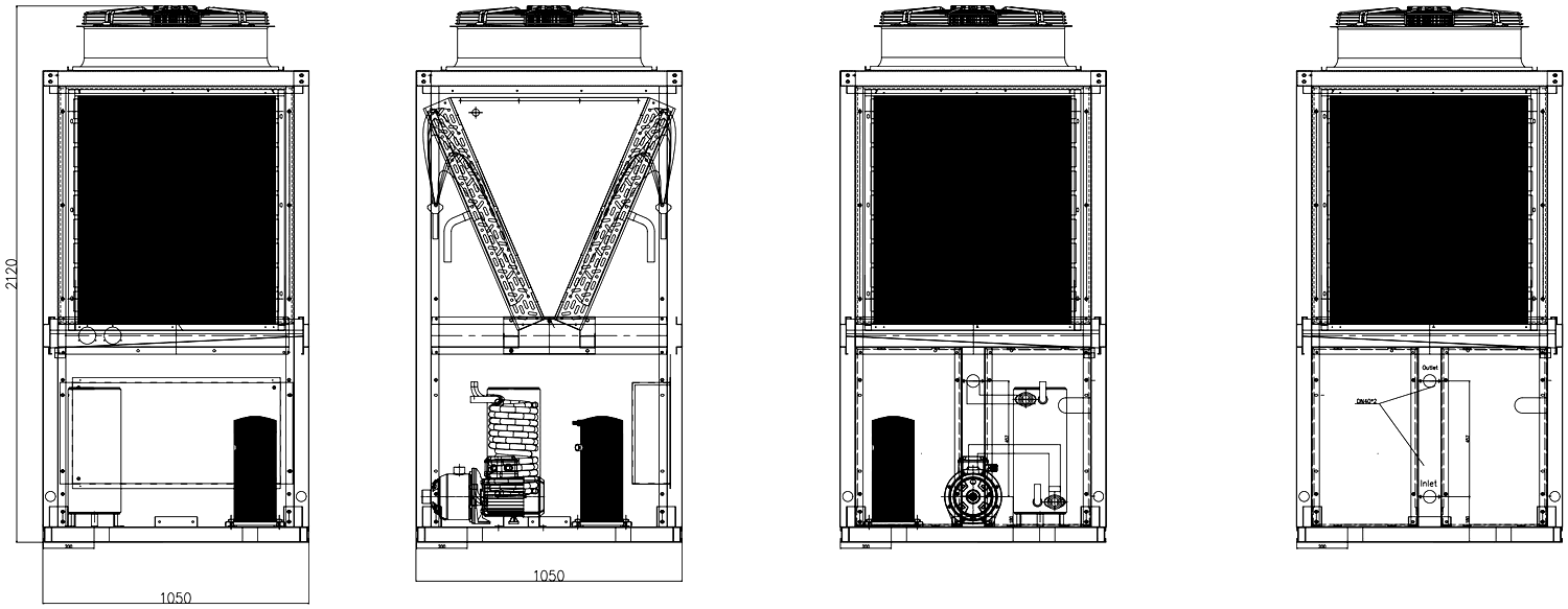
COP characteristic
Full performance map across the operating envelope| COP · hot water ↓ / Ambient °C → | -25 | -20 | -15 | -10 | -5 | 0 | 5 | 10 | 15 | 20 | 25 | 30 | 35 |
|---|---|---|---|---|---|---|---|---|---|---|---|---|---|
| 45 °C | 1.96 | 2.13 | 2.32 | 2.85 | 3.10 | 3.38 | 3.68 | 4.00 | 4.36 | 4.75 | 4.98 | 5.22 | 5.47 |
| 50 °C | 1.85 | 2.01 | 2.19 | 2.68 | 2.92 | 3.18 | 3.46 | 3.77 | 4.11 | 4.47 | 4.69 | 4.92 | 5.16 |
| 55 °C | 1.74 | 1.90 | 2.06 | 2.53 | 2.75 | 3.00 | 3.27 | 3.56 | 3.87 | 4.22 | 4.42 | 4.64 | 4.86 |
| 60 °C | 1.58 | 1.72 | 1.87 | 2.29 | 2.49 | 2.72 | 2.96 | 3.22 | 3.51 | 3.82 | 4.00 | 4.20 | 4.40 |
How to read this
- Performance map for the R410A EVI circuit, covering ambients down to −25 °C. Rated figures at the certified test conditions are on page 1.
- Where a figure on this map differs from the rated point on page 1, the map governs — it is measured across the full operating envelope, while the rated point is a single certified test condition.
Operating envelope
The compressor’s permitted window, in refrigeration terms| Evaporating temperature Te | −30 °C to 15 °C |
| Condensing temperature Tc | 20 °C to 68 °C |
| Peak condensing | 68 °C highest hot-water temperature the circuit can reach |
| Transient operation | Down to −30 °C Te permitted on start-up and defrost recovery, not continuously |
Reading the envelope
- Te (evaporating) follows the source the unit draws heat from — the colder the air or source water, the lower Te sits.
- Tc (condensing) follows the water leaving the unit — asking for 80 °C hot water puts Tc near the top of the envelope.
- A duty is valid only inside the shaded area. A cold source combined with very hot water pushes the point towards the top-left, which is exactly where the envelope closes in — that corner is the real limit on winter performance.
Representative envelope for the R410A EVI circuit, redrawn from Panasonic compressor data (Operating envelop.xlsx, sheet “R410a EVI”). Envelope limits are broadly similar across compressor makes, so treat this as a representation of the circuit’s operating window. Where a duty sits close to a boundary, confirm against the compressor fitted to the unit before finalising the design.
Documents & links
Scan with a phone camera, or tap the buttons

Documentation
Scan to open the latest revision on sunnivaencon.com


Connect & review
Product videos and customer feedback


SE-EVI-150V · Technical Data Sheet. Specifications are subject to change without prior notice.